Radar Principles
Why Self-driving Cars Specially Use Radar
- One of the biggest advantages of Radar is that: It measures the radial velocity directly, this helps to distinguish between stationary and moving objects.Other sensors need to calculate velocities by using derivatives.
- Also, Radar is less biased (less influenced) by environmental conditions, it can work day and night unlike cameras. It can work in rain and snow.
- Self-driving cars use a mixture of long and short range radars. In the context of automotive, radars are required to use only a specific frequency bandwidth. Automotive radars are cost-driven, small, and with less power consumption. It also should not contain moving parts.
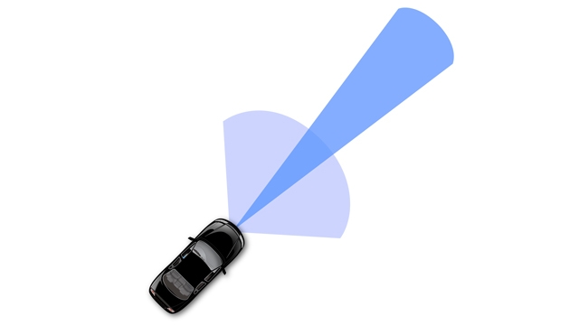
- Long range radars can reliably see objects up to 250 meters but they have a small field of view. On the other side, short range radars are designed to have a wider field of view.
Radars have been in use since 1930s when they were primarily used by the military to detect aircraft, but since then the radar technology has come a long way and today they are increasingly being used as automotive radar sensor for advanced driver assistance systems (ADAS). The image below shows how radar sensors are used along with a full suite of other sensors in an autonomous vehicle:

The advancements in the RF technologies and Digital Signal processing have made it possible to design efficient radars at low cost and in smaller sizes. The radar’s capability to determine the targets at long range with accurate velocity and spatial information make it an important sensor for self driving applications. Additionally, its capability to sense objects in dark and poor weather (rain, fog) conditions also help it cover the domains where LIDAR or camera may fail.
Radar Operation
A radar is composed of the following parts:
- A component that produces EM waves
- An antenna used to transmit and receive the radar signal
- A processing model for detecting the object properties
Radar works using the transmission and detection of electromagnetic waves as seen in the following image:

The electromagnetic waves are reflected if they meet an obstacle. If these reflected waves are received again at the place of their origin, then that means an obstacle is in the propagation direction.
The frequency of electromagnetic energy used for radar is unaffected by darkness and also penetrates fog and clouds. This permits radar systems to determine the position of road targets that are invisible to the naked eye because of distance, darkness, or weather.
Modern radar can extract widely more information from a target's echo signal than its range.

The automotive radars are small size sensors that can easily fit beneath the front grill or the bumper. As seen in the image above a radar module comprises of different parts.
- Radar Dome or Radome: A radome is a structural, weatherproof enclosure that protects a radar antenna. The radome is constructed of material that minimally attenuates the electromagnetic signal transmitted or received by the antenna, effectively transparent to radio waves.
- Radar Printed Circuit Board: This is analog hardware that includes the radar transceiver and antenna needed for radio wave generation.
- Printed Circuit Board and Processing: This includes the Digital Signal Processing (DSP) unit.

One can find many of articles comparing the LIDAR and RADAR, but in practice, these sensors are complementary to each other.
LIDAR can generate high resolution imaging based on reflection of the laser light off from the targets. But LIDARs fail in bad weather conditions as the very small wavelength doesn’t allow to work well in fog or rain. Additionally, LIDAR is an expensive sensor with costs varying from $35,000 to $100,000 as of 2019. Lidar is the preferred technology at Waymo.
Radar lacks the capability to generate a high resolution image, but it has highly accurate velocity estimation based on the doppler phenomenon, which we will cover in more detail later in this course. Also, radar wavelength allows it to sense the targets in bad weather conditions as well. Most important is the low manufacturing cost for a Radar. A radar unit can cost as low as a few hundred dollars, allowing a car manufacturer to deploy multiple Radar sensors for 360 degree perception. Tesla relies on Radar as its primary sensor and doesn’t include LIDAR in its sensor fusion system.
Reading: Delphi Develops Radar Sensor Alignment Algorithm for Automotive Active Safety System (used MATLAB and code generation to implement a radar safety system)
 https://www.mathworks.com/company/user_stories/delphi-develops-radar-sensor-alignment-algorithm-for-automotive-active-safety-system.html
- Some to the limitation of radar is that they can't provide precisely the object shapes.
- Radars are also not suitable for classification tasks as in the case of cameras.
- Lidars can provide a more accurate position and shape information, while radars are used to get motion information, and by combining the information from both of these sensor we will have a more robust object representation.
Signal Properties
In this concept, you will see a general overview of signal properties, including definitions of the wavelength of a signal and the general form for the equation of a signal.
Single Wave Parameters
Wavelength is the physical length from one point of a wave to the same point on the next wave, and it is calculated as
The higher the frequency the smaller the wavelength.

The frequency of a wave is the number of waves that pass by each second, and is measured in Hertz (Hz). The automotive radar generally operates at W band (76GHz - 81GHz). The signal at this frequency is referred to as millimeterWave since the wavelength is in mm.
The Bandwidth of a signal is the difference between the highest and the lowest frequency components in a continous band of frequencies.
The Amplitude is the strength of the signal. Often it corresponds to the power of the RF signal/electromagnetic field defined in dB/dBm. It is relevant while configuring the output power of the radar and sensing the received signal. Higher the amplitude of the Radar signal, more is the visibility of radar. Automotive Radar can operate at max of 55 dBm output power (316 W)


Phase of a Signal
Phase is a particular point in time on the cycle of a waveform, measured as an angle in degrees. A complete cycle is 360°. The phase for each argument value, relative to the start of the cycle, is shown in the image below, in degrees from 0° to 360° and in radians from 0 to 2π.
The frequency can also be defined as the first derivative of the phase with respect to the time.
This property will be used in measuring the doppler frequency shift for a moving target.

The difference between the phases of two periodic signals is called the phase difference. At values of when the difference is zero, the two signals are said to be in phase, otherwise they are out of phase with each other.
The phase information processing is important as we go through doppler processing as well as Angle of Arrival techniques for radar.

General Equation of a Wave

FMCW
FMCW radar (Frequency-Modulated Continuous Wave radar) is a special type of radar sensor which radiates continuous transmission power. FMCW radar’s ability to measure very small ranges to the target as well as its ability to measure simultaneously the target range and its relative velocity makes it the first choice type of radar for automotive applications.
A Chirp: Is a radar signal whose frequency in increasing (up chirp) or decreasing (down chirp) in time. Some radars use repeated chirp signals to compute both distance and velocity.


Additional Resources:
FMCW Hardware
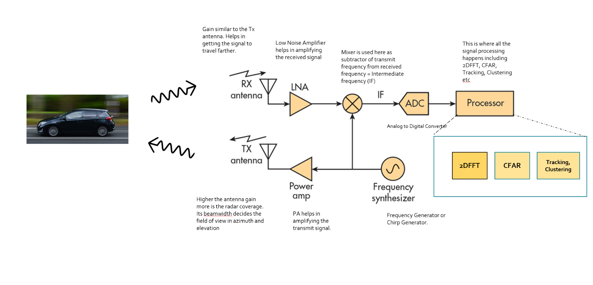
Frequency Synthesizer: The frequency synthesizer is the component that generates the frequency to bring the chirp frequency all the way to 77GHz in case of automotive radar.
Power Amp: The power amp amplifies the signal so the signal can reach long distance. Since the signal attenuates as it radiates, it needs higher power (amplitude) to reach targets at greater distances.
Antenna: The antenna converts the electrical energy into electromagnetic waves which radiate through the air, hit the target, and get reflected back toward the radar receiver antenna. The Antenna also increases the strength of the signal by focusing the energy in the desired direction. Additionally, the antenna pattern determines the field of view for the radar.
Mixer: In FMCW radar, the mixer multiplies the return signal with the sweeping signal generated by the frequency synthesizer. The operation works as frequency subtraction to give the frequency delta - also known as frequency shift or Intermediate frequency (IF). IF = Synthesizer Frequency - Return Signal Frequency.
Processor: The processor is the processing unit where all the Digital Signal processing, Detection, Tracking, Clustering, and other algorithms take place. This unit could be a microcontroller or even an FPGA.
As defined in the FMCW Hardware definitions, the antenna is a transducer that converts the electrical energy into electromagnetic waves. In the case of radar, these waves travel through the air and hit the target. Depending on the surface type and shape of the target, the waves get partially reflected back in the direction of the radar. The receiver antenna at the radar amplifies the received signal further and sends it to the receiver chain for further processing.
The Antenna Pattern
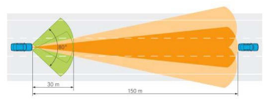
The antenna pattern is the geometric pattern of the strengths of the relative field emitted by the antenna.
The beamwidth of the antenna determines the field of view for the radar sensor. If the requirement for the radar is to just sense the targets in its own lane then the beamwidth needs to be small enough to cover the complete lane up to desired range. If the beamwidth is wider than the lane width, it will sense the targets in the other lanes as well.
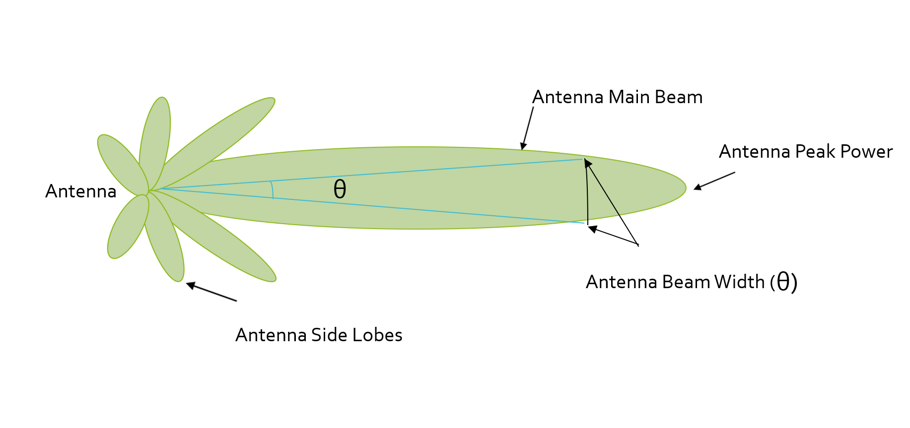
Antenna radiation not only comprises of the main beam but the sidelobes as well. Antenna sidelobes are critical because they can generate false alarms and pick interference from undesired direction. As seen in the pattern, the sidelobes of the antenna point in different directions and can sense targets that are not in the main beam. To avoid sidelobe detections it is critical to suppress the sidelobe levels to more than 30dB from the peak of the main beam.
Antenna Types
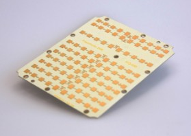
There are many types of antenna (dipole, patch, horn) that can be used at 77GHz, but the most commonly used antenna type in automotive radar is the patch antenna . The low cost, easy fabrication, and low profile of Patch Array Antennas makes them an ideal choice for automotive radar applications.
The antenna is composed of several patches, and the difference in signal received between different patches is used to compute the reflected angle.
Radar Cross Section
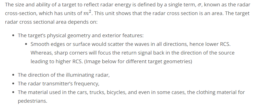
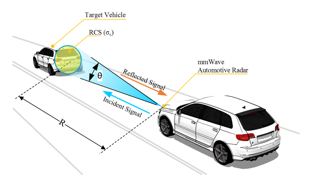
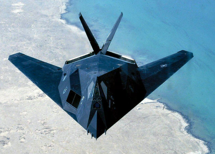
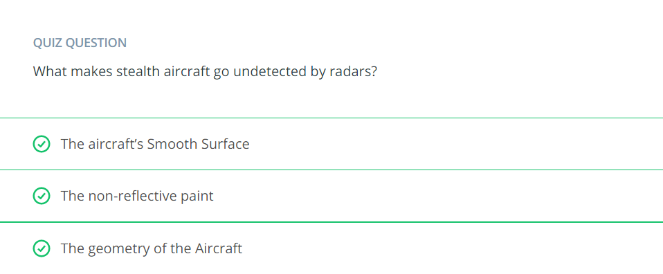
If absolutely all of the incident radar energy on the target were reflected equally in all directions, then the radar cross section would be equal to the target's cross-sectional area as seen by the transmitter. In practice, some energy is absorbed and the reflected energy is not distributed equally in all directions. Therefore, the radar cross-section is quite difficult to estimate and is normally determined by measurement.

RCS Units

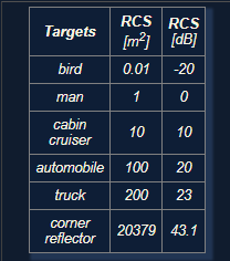
Quiz
Range Equation Overview
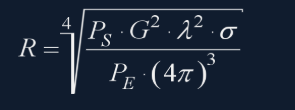
Using the Radar Range equation we can design the radar transmitter, receiver, and antenna to have the desired power, gain and noise performance to meet the range requirements.
A long range radar designed to cover 300m range and detect a target with smaller cross section would need higher transmit power and more antenna gain as compared to a short range radar designed to cover just 50m for similar target. A target with higher cross section can be detected at a longer range as compared to a target with smaller cross section.

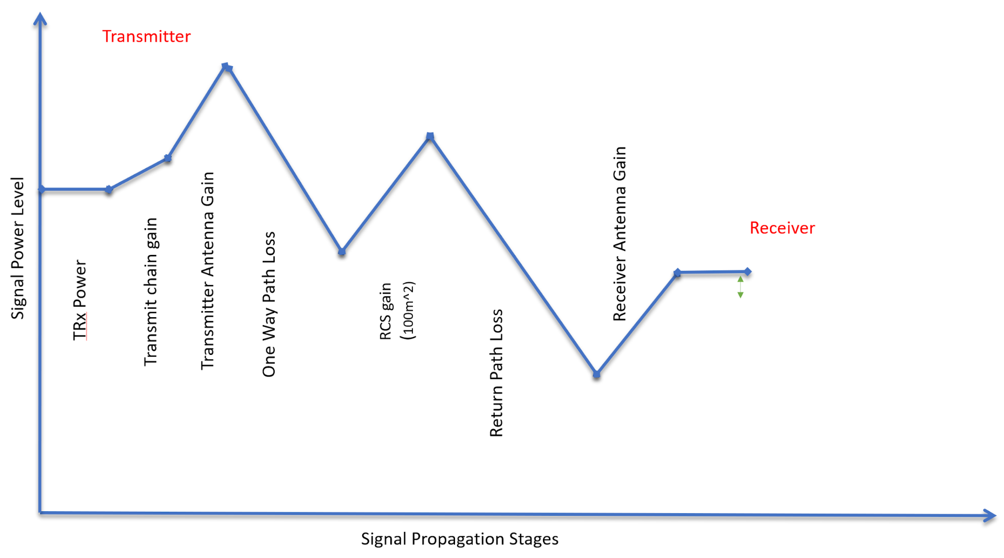
The image above shows the variation in the signal strength level :
- The transmitter power
- Power Amplifiers further increase the signal strength - Transmit chain gain
- Signal is further amplified using an antenna
- One Way Path Loss represents the loss in the signal strength as it travels towards the target
- On getting reflected from the target the signal gets amplified based on the RCS of the target
- After RCS gain the signal travel back towards the radar and has similar loss in strength as going forward
- The receiver antenna amplifies the return signal before sending it to the processing unit
Radar Detection
Below is an illustration showing the output of a radar's range detection. The peaks correspond to the strength of the return signal from targets and the frequency relates to the range. Relationship between frequency and range will be discussed in next lesson.
A radar cannot detect a signal that is below the noise level. The noise level is determined by the thermal noise generated by the receiver. To successfully detect a target, the return signal strength needs to be larger than the noise level. This is defined by a property called signal to noise ratio, or SNR.
SNR is a quantitative measure of a signal strength as compared to the level of noise. If the SNR is too low it becomes difficult for a radar to distinguish the signal from noise. Hence, higher SNR is desirable for successful detection of the target. Generally, a 7-13 dB SNR ensures successful detection in a road scenario.
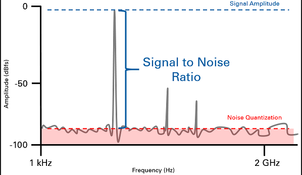
The image above shows the logarithmic value of SNR = power level (in dBm) - noise level (dBm). The plot shows the output of Range FFT (discussed in Lesson 2). In general, the higher the SNR value, the greater are the chances of successful Radar detection.